- Overview
- Operating The Preamp
- Specifications
- Literature
- Warranty
ATTENTION: For all International orders please email us for better freight options at sales@tridentaudiodevelopments.com
Overview
Trident Recording Studio’s started operations back in the 1960’s as a recording studio. Many things came out of the Recording Studio that led to what Trident Audio Developments is today.
Trident Recording Studios recorded legendary bands like David Bowie, The Beatles, James Taylor, Queen, Supertramp, Mott The Hoople, Bad Company, Free, Rush, Elton John, Manfred Mann, T-Rex and so many more, we simply do not have the space to list them all here. These recordings were done by incredible recording engineers like Roy Thomas Baker, Ken Scott, Tony Platt, Tony Visconti, Adam Moseley, Dave Hentschel, and many others. Trident Studios was the place known by the most famous bands as the place to record in London.
Trident studios were the first studio to acquire the first ever 8 Track from Ampex. No one in London had an 8 Track…not even EMI. When Trident got its first 16 track recorder, they decided to buy a new recording console but simply could not find any commercially available console to do 16 track recording with the feature set they needed. It was decided by the powers to be at Trident that between the recording engineers, and the technical staff under the direction of Barry Porter, Trident would attempt to build their own custom console.
The first console was designed purely for Trident Studios and was designated the ‘A’ Series. It was hand built to the need of the facilities and designed to be ergonomic. In those days, the integrated circuit (I.C.) had not been invented, so all the circuits used individual transistors (known as discrete design). This and the use of inductors in the lower and upper mid equaliser sections are said to account for much of the unique sound of the ‘A’ Series. From this first successful design was borne Trident Audio Developments Ltd, which went on to become a leading manufacturer of music recording consoles. One of the company’s earliest advertising slogans was ‘designed by recording engineers for recording engineers’.
This became a key component of what made the ‘Trident Sound’ unique. As a recording engineer rather than an electronics engineer, Trident Audio Developments was designed by the engineer’s ears, rather than a textbook of electronic design, and it is this, coupled with over thirty years’ experience that has enabled Trident Audio Developments to develop its own ‘philosophy of sound’ that is Trident’s trademark.
The “A” Series eventually led to the development of the “A“ Range Console, which became the console everyone wanted to work and record on. The “A“ Range was quickly labelled as the best sounding console ever. It should be noted, a large part of this sound, along with the legendary sounding EQ was the unique warm sound of the A-Range’s all discreate microphone preamplifiers.
There were only thirteen A Range consoles ever built back in the 1970’s, and almost all of them have been rebuilt and are still in use today, despite being nearly forty years old. This says a lot about the heritage of these iconic items of recording equipment and the artists that have used them.
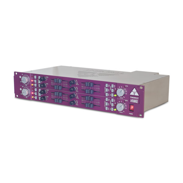
We hope you will enjoy the A Range 500 Series MIC PRE as much as we have enjoyed designing it.
Operating The Preamp
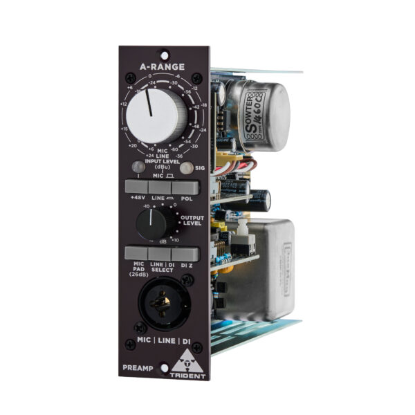
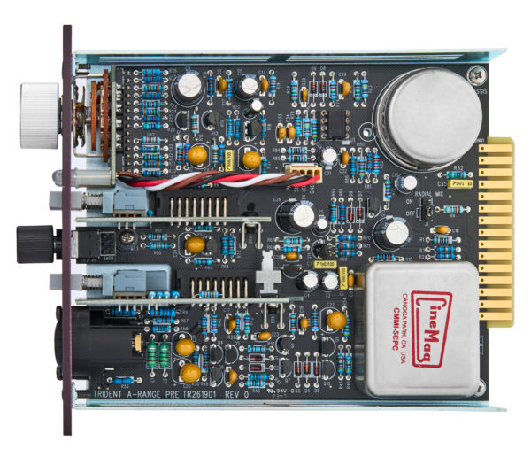
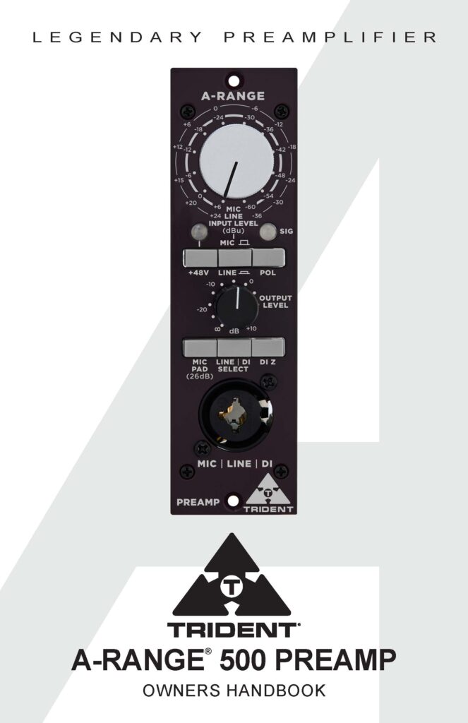
The input section of the A-Range® Mic Pre consists of a very high-quality transformer-coupled discrete microphone amplifier and discrete line amplifier designed specifically for professional audio applications. The microphone transformer is custom designed to the exact original Trident A-Range specifications. All outputs of the 500 Mic Preamp run through the output transformer.
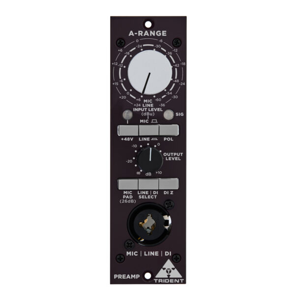
The microphone amplifier is designed to handle signal levels from –60dBu to as high as +6dBu without needing a separate pad switch. The 15-position combined mic/line gain switch is calibrated in accurate 6dB steps to provide precise matching of either microphone or line level signals. In conjunction with the ‘Output’ level control, very fine adjustment of signal level is achievable.
The preamplifier exhibits very low noise while maintaining extremely fast transient response and a frequency response that extends beyond 40kHz. Naturally, best results are achieved when using a high-quality condenser microphone. The microphone amplifier will also bring out the best in dynamic and ribbon microphones.
The front panel XLR is paralleled to the rear connector XLR input, providing the option of either microphone input through a lunchbox power supply such as a Trident Decadent or directly via the mic pre front panel.
When connecting a microphone to the Mic Preamp, set the ‘Input Level’ rotary switch to its minimum (‘+6’) position and the ‘Output’ level control to its ‘0’ position. The ‘Mic / Line’ switch should not be depressed. If required, engage the ‘+48V’ phantom power switch while the ‘Input Level’ control is at minimum. The associated LED will show that phantom power is present. Allow up to 30 seconds for the microphone to reach normal operating level and advance the ‘Input Level’ control until a suitable level is achieved at the output of the unit. The ‘Sig’ LED signal indicator at the output stage of the circuit is designed to illuminate red when a signal level of +17dBu occurs at either the input or output stage (4dB before actual internal signal clipping), this will otherwise illuminate a varying intensity green when a signal is present. This provides plenty of overload margin as the A-Range® is capable of very high output levels (up to +22dBu) into a balanced load. However, by setting the level as described above, adequate headroom is maintained and there should be no danger of overloading following equipment.
Technical Specifications
Power : +16V =18mA, -16V=14mA
+48V=13mA (Max 27mA when Phantom activated)
Microphone Input to Output
Input Impedance : 1.5KΩ
Gain : Variable -∞ to +70dB (Input gain -6dB to +60dB and Output gain from -∞ to +10dB).
Bandwidth Min Gain : 12Hz to 75KHz (+/- 0.5dB 20Hz to 15KHz) – Output level at max and input level at min).
Bandwidth Max Gain : 15Hz to 70KHz (+/- 0.5dB 20Hz to 15KHz) – Output level at max and input level at max).
Distortion : THD + Noise = 0.02% 100Hz to 20KHz (+15dBu Output).
EIN : Better than -126dBu @+70dB gain with 150Ω input load.
Noise : -94dBu (Measured at Min Input Level and O/P level set at 0dB gain (22Hz/22KHz)
Max Output : +22dBu.
Line Input
Input Impedance : >20KΩ
Gain : Variable -∞ to +46dB (Input level -24dB to +36dB and Output level from -∞ to +10dB).
Bandwidth Min Gain : >100KHz (Output level at max and input level at min).
Bandwidth Max Gain : > 70KHz (Output level at max and input level at max).
Distortion : THD + Noise = < 0.05%
Noise : -87dBu (22Hz/22KHz filtered) – Output at Max.
Max Output : +22dBu
Hi-Z Line Input
Input Impedance : Front panel switchable unbalanced 500KΩ to 5MΩ Internally range can be switched from 500KΩ/2.5MΩ or 1MΩ/5MΩ.
Gain : Variable -∞ to +58dB (Input level -3dB to +48dB and Output level from -∞ to +10dB).
Distortion : <0.06% @+15dBu output.
Noise : -94dBu (Min Input level) to -43dBu (Max Input Level) – With Output level set a unity (0) level.
* In the interests of product development, Trident Audio may change technical specifications without notice.
Download Trident A-RANGE 500 Preamp Literature
Trident Electronics Warranty
Trident Audio Developments Limited Warranty Statement
The following outlines the warranty periods for all Trident Analogue electronics. All warranty service requires Proof of Purchase. Proof of purchase is the original Bill of Sale or Sales Invoice from an authorized dealer.
Trident Audio Developments electronics are covered by a limited warranty against defects in materials and workmanship (parts and labor) for a period of One (1) Year from the date the unit is sold to the Dealer or original purchaser only.
Acceptable registration is met by registering online – click here
The terms and conditions of this limited warranty are:
- The warranty applies to Trident Audio Developments Electronics purchased from Trident Audio or authorized Trident Audio dealers.
- The warranty covers any defects in materials and workmanship and is limited to the repair or replacement of the original registered product. In its sole discretion, Trident may either repair or replace the product with a product of the same model or replace the product with a new model of a similar specification when the same model is no longer available.
- The warranty does not cover any of the following: damage caused by the user: spillages or moisture damage; neglect, abuse, or misuse, including but not limited to the failure to use the product(s) for its normal purpose in accordance with the manufacturer’s instructions for use. Failure to properly maintain the product in accordance with the manufacturer’s instructions, and/or the failure to use the products in accordance with the manufacturer’s specifications; normal wear and tear; use of products with incompatible or faulty equipment; unauthorized modifications; repairs conducted by unauthorized persons or service center’s; the model and/or serial number is altered, removed or made illegible; accidents; acts of God or any cause beyond the control of Trident Audio Developments. It does not cover damage caused by connecting to an improper power voltage supply, cosmetic defects, such as paint finish, and general wear and tear, as well as certain consumables not covered under warranty such as fuses, faders, pots, switches, and meter bulbs. Mechanical components including but are not limited to a consumable item; potentiometers, faders, and switches are covered by a 90-day warranty. Failure to maintain, damage; neglect, abuse, or misuse of any mechanical components in this time will result in a void warranty. Trident recommends regular service of the product and in particular; regular service of the mechanical components such as potentiometers and faders.
- The warranty is applicable to the original purchaser throughout the warranty period as stated above or until the original owner resells the product. If a unit is received for warranty repair, and after complete examination and testing, no problem is found with the unit, the customer will be charged for time labor plus return shipping costs, presuming initial user error falsely caused the unit to be determined faulty.
- The warranty does not affect any statutory rights the original purchaser may have in accordance with the law applicable in the jurisdiction where the product was purchased, or any rights the original purchaser may have against the authorized dealer pursuant to their original purchase agreement. This warranty gives you specific legal rights and you may also have other rights, which vary from state to state, and or country to country.Any claim pursuant to this warranty from the date of purchase of any Trident Audio Developments product must be returned, together with the original proof of purchase, to the authorized Trident Audio dealer that sold the product, or to the Trident Audio service center in the USA or our UK service center. All returns to Trident Audio, or any Trident Audio Service Center must be in the original packing, accompanied by the issued Repair Authorization, and must be shipped to the address specified on the Return Authorization via insured freight at the customer’s own expense. Factory original packaging can be ordered from Trident Audio, Inc. Customer will be charged for new factory original packaging if the customer fails to ship product to Trident Audio in the original factory packaging. Trident Audio will not pay for express or overnight delivery.
- Once the product has been received, the authorized Trident Audio service center will assess the warranty claim and arrange to either repair or replace it in accordance with the warranty procedure prescribed by Trident Audio for their authorized service center network. The warranty replacement will be conducted by the authorized Trident Audio service center as promptly as possible and within a reasonable time from the date of submission of the warranty claim. In all circumstances, a claimant under this warranty will be liable for all costs in delivering their Trident Audio brand product to the authorized service center for warranty replacement and for all costs in collecting the repaired/replacement Trident Audio product from that authorized Trident Audio service center. Trident Audio service center may waive the cost of return shipping after full inspection to determine the cause of the warranty.
- Trident Audio will not accept any warranty replacement without the original proof of purchase of the Trident Audio product, and without the registration of the Trident Audio product within 30 days of purchase by mail, or online. It is the original purchaser’s responsibility to keep the original proof of purchase or copy safe at all times, as Trident Audio is not obliged to provide a replacement of the original proof of purchase.
- The warrantor assumes no liability for property damage or any other incidental or consequential damage whatsoever which may result from the failure of this product.
- A Trident Audio product that was not purchased through an authorized and legitimate sales channel is considered “Grey Market”. Warranties for Trident Audio Products purchased outside the USA will be covered by its Trident Audio UK Service Center. Trident Audio product originally sold to the USA market and consequently resold overseas forfeits its warranty. “Grey Market” purchases are not covered by any warranty. In the case that a Trident Audio Product must be returned, it should be returned to the original place of purchase, or the Trident Audio factory, with a proper return authorization. Returns from outside the USA, the customer shall adhere to specific shipping, customs, and commercial invoicing instructions given with the Return Authorization. Trident Audio will not be responsible for transportation costs or customs fees related to any importation or reexportation charges whatsoever.
- Trident Audio shall not be liable for damages in excess of the purchase price of the Trident Audio product arising out of the use or inability to use the Trident Audio product.
Governing Laws
Any dispute, controversy or claim arising out of or relating to this Agreement shall be decided by arbitration in Los Angeles, California, in accordance with the rules of the American Arbitration Association (the “Association) then in effect. Any award rendered by the Association shall be final, binding and not subject to appeal, and may be enforced by any court of competent jurisdiction.
For Tech Support and Repair Authorization, please contact: US Service & Sales 1845 W. 169th Street Gardena, CA 90247 at +1 (310) 323-9050 or sales@tridentaudiodevelopments.com
Trident Audio Developments is a registered trademark of PMI Audio Group
©2010 PMI Audio GroupFeatures and specifications are subject to change without notice.
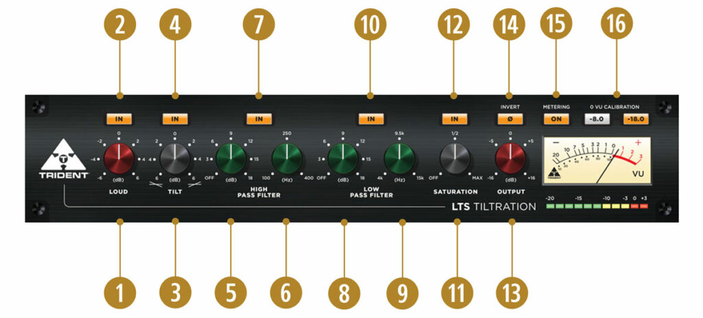
Plug-in Features and Controls
1. LOUD
A color-coded (red) knob provides controls for loudness compensation within the range of -6 to +6 (cut/boost intensity level). Click the knob and drag up to increase the value and drag down to decrease. Alternatively, double-click on the rotary knob to manually enter a value.
2. LOUD BYPASS
Press the IN button above the LOUD control to enable (backlight on) or disable (backlight off) the loudness compensation function.
3. TILT
A color-coded (black) knob provides controls for tilt equalization within the range of -6 to +6 (cut/boost intensity level). Click the knob and drag up to increase the value (favoring high frequencies) and drag down to decrease (favoring low frequencies). Alternatively, double-click on the rotary knob to manually enter a value.
4. TILT BYPASS
Press the IN button above the TILT control to enable (backlight on) or disable (backlight off) the Tilt equalization function.
5. HIGH PASS FILTER – Slope (dB)
A color-coded (green) rotary knob sets the high pass filter slope in dB per octave, within the range of 0 dB/Off (Off=default) to 18 dB. Click the knob and drag up to increase the value and drag down to decrease. Alternatively, double-click on the rotary knob to manually enter a value.
6. HIGH PASS FILTER – Frequency (Hz)
A color-coded (green) rotary knob sets the high pass corner frequency within the range of 100 Hz to 400 Hz. Click the knob and drag up to increase the frequency and drag down to decrease. Alternatively, double-click on the rotary knob to manually enter a value.
7. HIGH PASS FILTER – Bypass
Press the IN button above the HPF controls to enable (backlight on) or disable (backlight off) the high pass filter function.
8. LOW PASS FILTER – Slope (dB)
A color-coded (green) rotary knob sets the low pass filter slope in dB per octave, within the range of 0 dB/Off (Off=default) to 18 dB. Click the knob and drag up to increase the value and drag down to decrease. Alternatively, double-click on the rotary knob to manually enter a value.
9. LOW PASS FILTER – Frequency (Hz)
A color-coded (green) rotary knob sets the low pass filter corner frequency within 4 kHz to 15 kHz. Click the knob and drag up to increase the frequency and drag down to decrease. Alternatively, double-click on the rotary knob to manually enter a value.
10. LOW PASS FILTER – Bypass
Press the IN button above the LPF controls to enable (backlight on) or disable (backlight off) the low pass filter function.
11. SATURATION
A color-coded (black) rotary knob sets the saturation enhancement level within the range of 0 (MIN) and 100 (MAX). Click the knob and drag up to increase the value and drag down to decrease. Alternatively, double-click on the rotary knob to manually enter a value.
12. SATURATION Bypass
Press the IN button above the SATURATION control to enable (backlight on) or disable (backlight off) the saturation enhancement function.
13. OUTPUT
A color-coded (red) rotary knob sets the output gain level within the range of -16 dB to +16 dB. Click the knob and drag up to increase the value and drag down to decrease. Alternatively, double-click on the rotary knob to manually enter a value.
14. POLARITY (Ø)
Press the Ø button above the OUTPUT control to invert the signal polarity (backlight on) or maintain the current polarity (backlight off).
15. METERING
Press the ON button above the VU meter to enable (backlight on) or disable (backlight off) the VU and PPM metering functions.
16. 0 VU CALIBRATION
Use the -8.0 or -18.0 radio buttons above the VU meter to toggle between a 0 VU calibration level of -8.0 dBFS or -18 dBFS respectively. NOTE: Calibration applies to the VU meter only; the PPM meter range is mapped directly to peak values between -20 and +3 dBFS.
iLok License Manager is used for software activation (2 activations per license). For more information about iLok License Manager, please visit ilok.com.
