- Overview
- Operating The Equalizer
- Specifications
- Literature
- Warranty
ATTENTION: For all International orders please email us for better freight options at sales@tridentaudiodevelopments.com
SHIPPING DECEMBER
Overview
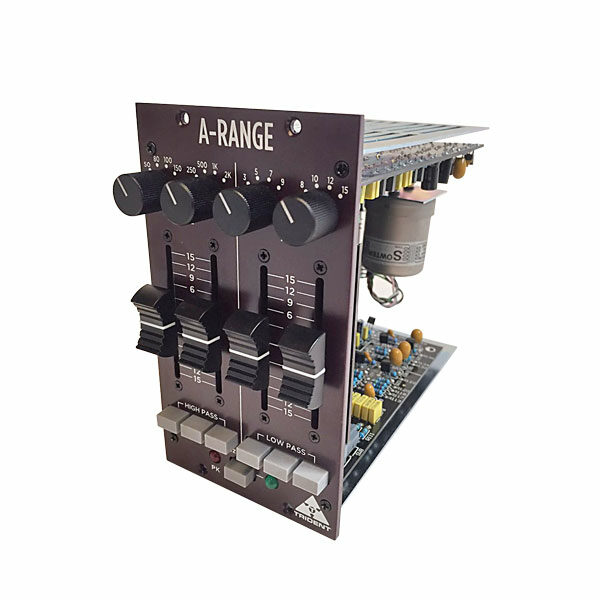
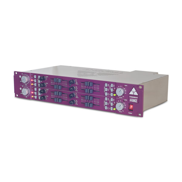
The legendary A-Range® equalizer holds a unique place in audio history, with a stunningly musical sound that resulted from its all-discrete transistor circuitry and the use of inductors in the upper and lower mid bands. The A-Range® is a faithful re-creation of the original four band Trident A-Range® equalizer in a 500 module format, that will add the unique Trident signature to any programme material.
Download the A-Range® 500 User Manual here.
Introduction
The legendary A-Range® equaliser holds a unique place in audio history, with a stunningly musical sound that resulted from its all-discrete transistor circuitry and the use of inductors in the upper and lower mid bands. The A-Range® s a faithful re-creation of the original four band Trident A-Range® equaliser in a 500 module format, that will add the unique Trident signature to any programme material.
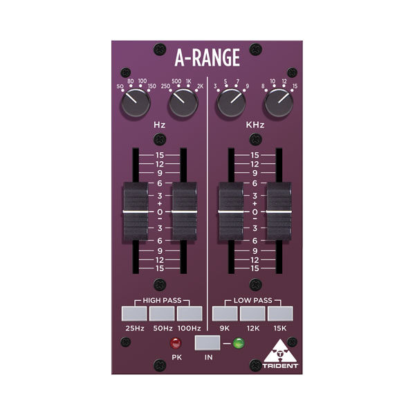
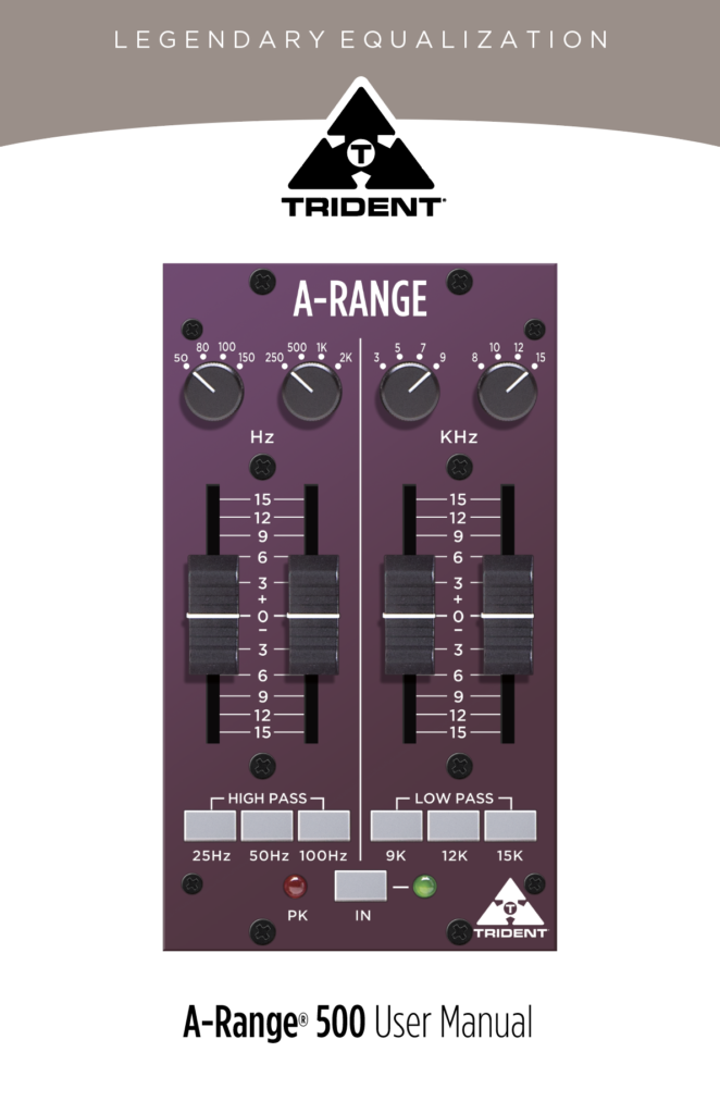
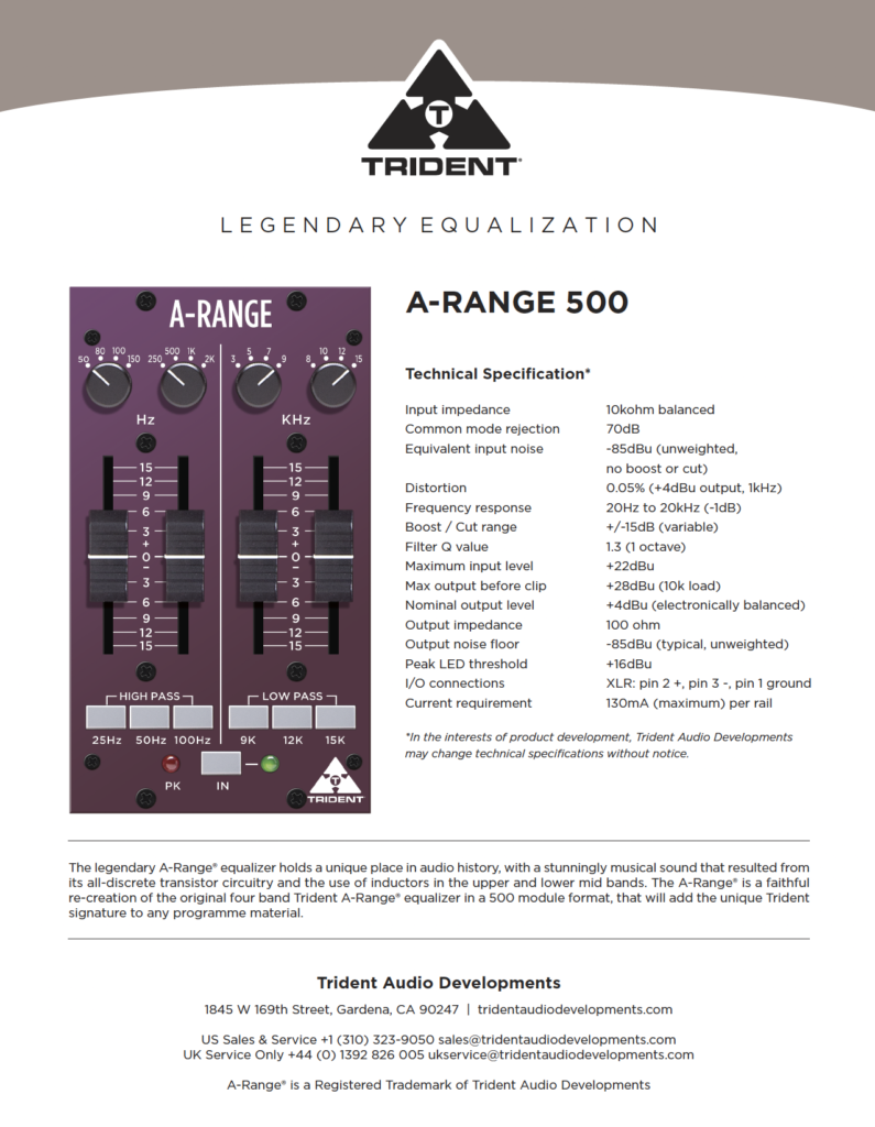
The mid frequency EQ sections are “peaking”, while the high and low frequency sections are “shelving”. A distinguishing feature of both the original A-Range® console and this module, is the use of faders for level adjustment, rather than rotary potentiometers. These faders feature a useful centre detent at mid travel to denote zero boost or cut of the selected frequency. The use of faders makes it very easy to see not only how much equalisation is being applied. Each band is rotary-switch-selectable to one of four frequencies, while individual push buttons engage the three high pass and three low pass filters. An LED peak level indicator is included to warn when levels get too high. The Line level input and output are balanced for maximum signal integrity & high output levels with minimum distortion.
The difference between shelving and peaking equalisers are as follows. A shelving equaliser boosts or cuts all frequencies equally, above or below a certain frequency, usually the point where it effectively reaches its “shelf” state. A “high shelf” EQ boosts or cuts high frequencies and a “low shelf” type boosts or cuts low frequencies. This type of circuit is very popular in hi-fi systems but is also actually highly musical when applied in a recording environment. In contrast, a peaking equaliser is one that, as its name implies, has a centre frequency that is boosted or attenuated more than others. The frequency range over which it reaches its peak and then falls down is known as the bandwidth (or “Q”). Because this type of design reaches a peak and then falls away, it is possible with this type of circuit to “home in” on particular frequencies and make adjustments without affecting those around them. This can be particularly useful when working with instruments such as bass guitars and snare drums. By incorporating both shelving and peaking equalisers into the design of the versatile A-Range®, it is possible to get the best of both types of design.
Operating The Equaliser
Begin with all boost/cut faders set to their mid way (‘0’) positions. Adjust the low and high mid frequency controls to their minimum positions (fully anticlockwise). The high and low pass filter switches should be in their out positions. Set the frequency select switches controlling the high and low shelving sections, to 150Hz and 12kHz respectively. Lastly,press the ‘IN’ switch (the associated green LED will light).
Pushing up any of the four faders beneath its associated frequency select switch, will result in the chosen frequency being boosted. Moving the faders below centre will result in the chosen frequency being cut. Operating the frequency select switch in the high section (8kHz to 15kHz shelving) will introduce a subtle change of emphasis. Operating the frequency select switch in the upper mid section (3kHz to 9kHz peaking) will introduce a distinct difference according to the frequency selected, since it is now peaking rather than shelving and also due to the characteristics of the inductor-based circuitry. Operating the frequency select switch in the ‘lower mid’ section, 250Hz to 2kHz peaking, will also introduce a distinct difference according to the frequency selected, again because of its peaking nature and the use of inductors in this part of the circuit.
Operating the frequency select switch in the low section, 80Hz to 150Hz shelving, will introduce an effective change of emphasis to the low frequencies.
Finally, the three shelving ‘low-pass’ and ‘high-pass’ filter sections are employed to introduce a roll-off of either high frequencies or low frequencies respectively, according to which of the three push buttons are selected in each section. The high-pass filters are useful for the minimization of extraneous low frequency ‘rumble’ caused, for example, by someone’s feet moving about near a microphone stand, nearby traffic noise, AC systems, etc. Additionally, a high-pass filter can be used effectively during recording to reduce the accumulation of low frequency sounds that can adversely affect a mix. The three high-pass corner frequencies are 25Hz, 50Hz and 100Hz. The low-pass filters are used to minimize high frequency noise that may cause ‘harshness’ in a vocal, or to tame the output of a violin or guitar amplifier, etc. Low-pass filtering is often employed on kick and snare drums and bass guitars, as well as a means of reducing ‘hiss’. The three lowpass filter frequencies on the A-Range® are 9k, 12k and 15k. Filters can also be used in combination for greater effect.
The amount of boost or cut required for any particular programme material is a very subjective matter and is usually found by experiment. Use the ‘IN’ switch to make comparisons between EQ’d and non-EQ’d signals. Keep an eye on the red “PK” LED: occasional flashes are OK but if it is on all the time, turn down the input level to the A-Range® module. using whatever modules precede it in the signal chain.
Extended Function
If you have a Radial Work horse™ or compatible rack, you can send the output of the A-Range® to the rack’s internal mix buss. To do this, locate jumper J1 on the main circuit board near the edge connector. Move the jumper onto the two pins nearest R53.
Technical Specifications
Input impedance: 10kohm balanced
Common mode rejection: 70dB
Equivalent input noise: -85dBu (unweighted, no boost or cut)
Distortion: 0.05% (+4dBu output, 1kHz)
Frequency response: 20Hz to 20kHz (-1dB)
Boost / Cut range: +/-15dB (variable)
Filter Q value: 1.3 (1 octave)
Maximum input level: +22dBu
Max output before clip: +28dBu (10k load)
Nominal output level: +4dBu (electronically balanced)
Output impedance: 100 ohm
Output noise floor: -85dBu (typical, unweighted)
Peak LED threshold: +16dBu
I/O connections XLR: pin 2 +, pin 3 -, pin 1 ground
Current requirement: 130mA (maximum) per rail
*In the interests of product development, Trident Audio Developments may change technical specifications without notice.
Download Trident A-RANGE 500 Literature
Trident Electronics Warranty
Trident Audio Developments Limited Warranty Statement
The following outlines the warranty periods for all Trident Analogue electronics. All warranty service requires Proof of Purchase. Proof of purchase is the original Bill of Sale or Sales Invoice from an authorized dealer.
Trident Audio Developments electronics are covered by a limited warranty against defects in materials and workmanship (parts and labor) for a period of One (1) Year from the date the unit is sold to the Dealer or original purchaser only.
Acceptable registration is met by registering online – click here
The terms and conditions of this limited warranty are:
- The warranty applies to Trident Audio Developments Electronics purchased from Trident Audio or authorized Trident Audio dealers.
- The warranty covers any defects in materials and workmanship and is limited to the repair or replacement of the original registered product. In its sole discretion, Trident may either repair or replace the product with a product of the same model or replace the product with a new model of a similar specification when the same model is no longer available.
- The warranty does not cover any of the following: damage caused by the user: spillages or moisture damage; neglect, abuse, or misuse, including but not limited to the failure to use the product(s) for its normal purpose in accordance with the manufacturer’s instructions for use. Failure to properly maintain the product in accordance with the manufacturer’s instructions, and/or the failure to use the products in accordance with the manufacturer’s specifications; normal wear and tear; use of products with incompatible or faulty equipment; unauthorized modifications; repairs conducted by unauthorized persons or service center’s; the model and/or serial number is altered, removed or made illegible; accidents; acts of God or any cause beyond the control of Trident Audio Developments. It does not cover damage caused by connecting to an improper power voltage supply, cosmetic defects, such as paint finish, and general wear and tear, as well as certain consumables not covered under warranty such as fuses, faders, pots, switches, and meter bulbs. Mechanical components including but are not limited to a consumable item; potentiometers, faders, and switches are covered by a 90-day warranty. Failure to maintain, damage; neglect, abuse, or misuse of any mechanical components in this time will result in a void warranty. Trident recommends regular service of the product and in particular; regular service of the mechanical components such as potentiometers and faders.
- The warranty is applicable to the original purchaser throughout the warranty period as stated above or until the original owner resells the product. If a unit is received for warranty repair, and after complete examination and testing, no problem is found with the unit, the customer will be charged for time labor plus return shipping costs, presuming initial user error falsely caused the unit to be determined faulty.
- The warranty does not affect any statutory rights the original purchaser may have in accordance with the law applicable in the jurisdiction where the product was purchased, or any rights the original purchaser may have against the authorized dealer pursuant to their original purchase agreement. This warranty gives you specific legal rights and you may also have other rights, which vary from state to state, and or country to country.Any claim pursuant to this warranty from the date of purchase of any Trident Audio Developments product must be returned, together with the original proof of purchase, to the authorized Trident Audio dealer that sold the product, or to the Trident Audio service center in the USA or our UK service center. All returns to Trident Audio, or any Trident Audio Service Center must be in the original packing, accompanied by the issued Repair Authorization, and must be shipped to the address specified on the Return Authorization via insured freight at the customer’s own expense. Factory original packaging can be ordered from Trident Audio, Inc. Customer will be charged for new factory original packaging if the customer fails to ship product to Trident Audio in the original factory packaging. Trident Audio will not pay for express or overnight delivery.
- Once the product has been received, the authorized Trident Audio service center will assess the warranty claim and arrange to either repair or replace it in accordance with the warranty procedure prescribed by Trident Audio for their authorized service center network. The warranty replacement will be conducted by the authorized Trident Audio service center as promptly as possible and within a reasonable time from the date of submission of the warranty claim. In all circumstances, a claimant under this warranty will be liable for all costs in delivering their Trident Audio brand product to the authorized service center for warranty replacement and for all costs in collecting the repaired/replacement Trident Audio product from that authorized Trident Audio service center. Trident Audio service center may waive the cost of return shipping after full inspection to determine the cause of the warranty.
- Trident Audio will not accept any warranty replacement without the original proof of purchase of the Trident Audio product, and without the registration of the Trident Audio product within 30 days of purchase by mail, or online. It is the original purchaser’s responsibility to keep the original proof of purchase or copy safe at all times, as Trident Audio is not obliged to provide a replacement of the original proof of purchase.
- The warrantor assumes no liability for property damage or any other incidental or consequential damage whatsoever which may result from the failure of this product.
- A Trident Audio product that was not purchased through an authorized and legitimate sales channel is considered “Grey Market”. Warranties for Trident Audio Products purchased outside the USA will be covered by its Trident Audio UK Service Center. Trident Audio product originally sold to the USA market and consequently resold overseas forfeits its warranty. “Grey Market” purchases are not covered by any warranty. In the case that a Trident Audio Product must be returned, it should be returned to the original place of purchase, or the Trident Audio factory, with a proper return authorization. Returns from outside the USA, the customer shall adhere to specific shipping, customs, and commercial invoicing instructions given with the Return Authorization. Trident Audio will not be responsible for transportation costs or customs fees related to any importation or reexportation charges whatsoever.
- Trident Audio shall not be liable for damages in excess of the purchase price of the Trident Audio product arising out of the use or inability to use the Trident Audio product.
Governing Laws
Any dispute, controversy or claim arising out of or relating to this Agreement shall be decided by arbitration in Los Angeles, California, in accordance with the rules of the American Arbitration Association (the “Association) then in effect. Any award rendered by the Association shall be final, binding and not subject to appeal, and may be enforced by any court of competent jurisdiction.
For Tech Support and Repair Authorization, please contact: US Service & Sales 1845 W. 169th Street Gardena, CA 90247 at +1 (310) 323-9050 or sales@tridentaudiodevelopments.com
Trident Audio Developments is a registered trademark of PMI Audio Group
©2010 PMI Audio GroupFeatures and specifications are subject to change without notice.
Plug-in Features and Controls
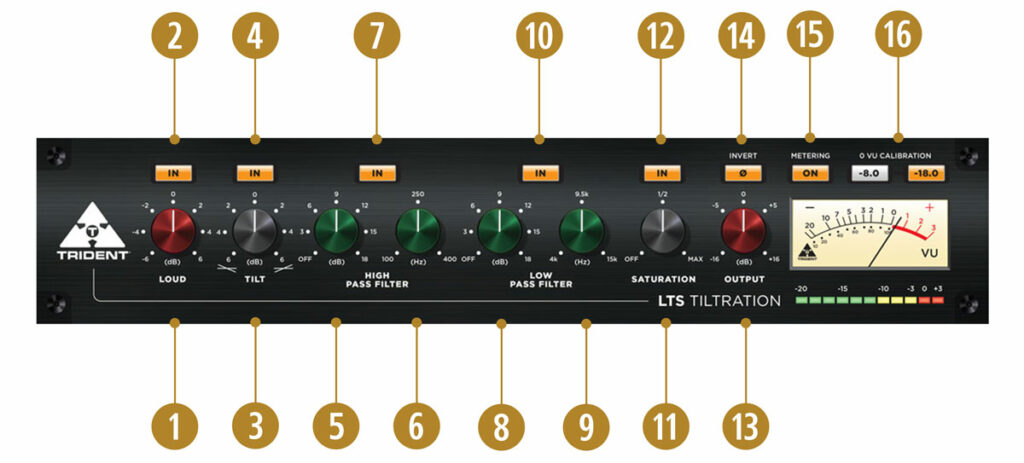
1. LOUD
A color-coded (red) knob provides controls for loudness compensation within the range of -6 to +6 (cut/boost intensity level). Click the knob and drag up to increase the value and drag down to decrease. Alternatively, double-click on the rotary knob to manually enter a value.
2. LOUD BYPASS
Press the IN button above the LOUD control to enable (backlight on) or disable (backlight off) the loudness compensation function.
3. TILT
A color-coded (black) knob provides controls for tilt equalization within the range of -6 to +6 (cut/boost intensity level). Click the knob and drag up to increase the value (favoring high frequencies) and drag down to decrease (favoring low frequencies). Alternatively, double-click on the rotary knob to manually enter a value.
4. TILT BYPASS
Press the IN button above the TILT control to enable (backlight on) or disable (backlight off) the Tilt equalization function.
5. HIGH PASS FILTER – Slope (dB)
A color-coded (green) rotary knob sets the high pass filter slope in dB per octave, within the range of 0 dB/Off (Off=default) to 18 dB. Click the knob and drag up to increase the value and drag down to decrease. Alternatively, double-click on the rotary knob to manually enter a value.
6. HIGH PASS FILTER – Frequency (Hz)
A color-coded (green) rotary knob sets the high pass corner frequency within the range of 100 Hz to 400 Hz. Click the knob and drag up to increase the frequency and drag down to decrease. Alternatively, double-click on the rotary knob to manually enter a value.
7. HIGH PASS FILTER – Bypass
Press the IN button above the HPF controls to enable (backlight on) or disable (backlight off) the high pass filter function.
8. LOW PASS FILTER – Slope (dB)
A color-coded (green) rotary knob sets the low pass filter slope in dB per octave, within the range of 0 dB/Off (Off=default) to 18 dB. Click the knob and drag up to increase the value and drag down to decrease. Alternatively, double-click on the rotary knob to manually enter a value.
9. LOW PASS FILTER – Frequency (Hz)
A color-coded (green) rotary knob sets the low pass filter corner frequency within 4 kHz to 15 kHz. Click the knob and drag up to increase the frequency and drag down to decrease. Alternatively, double-click on the rotary knob to manually enter a value.
10. LOW PASS FILTER – Bypass
Press the IN button above the LPF controls to enable (backlight on) or disable (backlight off) the low pass filter function.
11. SATURATION
A color-coded (black) rotary knob sets the saturation enhancement level within the range of 0 (MIN) and 100 (MAX). Click the knob and drag up to increase the value and drag down to decrease. Alternatively, double-click on the rotary knob to manually enter a value.
12. SATURATION Bypass
Press the IN button above the SATURATION control to enable (backlight on) or disable (backlight off) the saturation enhancement function.
13. OUTPUT
A color-coded (red) rotary knob sets the output gain level within the range of -16 dB to +16 dB. Click the knob and drag up to increase the value and drag down to decrease. Alternatively, double-click on the rotary knob to manually enter a value.
14. POLARITY (Ø)
Press the Ø button above the OUTPUT control to invert the signal polarity (backlight on) or maintain the current polarity (backlight off).
15. METERING
Press the ON button above the VU meter to enable (backlight on) or disable (backlight off) the VU and PPM metering functions.
16. 0 VU CALIBRATION
Use the -8.0 or -18.0 radio buttons above the VU meter to toggle between a 0 VU calibration level of -8.0 dBFS or -18 dBFS respectively. NOTE: Calibration applies to the VU meter only; the PPM meter range is mapped directly to peak values between -20 and +3 dBFS.
iLok License Manager is used for software activation (2 activations per license). For more information about iLok License Manager, please visit ilok.com.
